Table of Contents
01 Why Power Stability Matters | 02 LED Lamp Bead Damage | 03 Driver IC Failure | 04 Control System Damage | 05 Wiring & Structural Damage | 06 Display Abnormalities | 07 Long-Term Reliability | 08 Prevention Measures | ✓ Power Supply Checklist | FAQ
Stable power delivery is the single most important factor in LED display longevity — and the most consistently underestimated. A power supply fault does not just interrupt the display. It destroys hardware. LED lamp beads, driver ICs, sending cards, receiving cards, and wiring are all at risk from a single voltage surge event. This guide explains every category of power-related damage, the specific mechanism behind each, and the practical prevention measures that eliminate the risk before failure occurs.
Every component inside an LED display — LED lamp beads, driver ICs, sending cards, receiving cards, and the PCB traces connecting them — operates within a defined voltage and current tolerance range. When the power supply delivers voltage or current outside that range, components degrade or fail immediately. There is no intermediate state: once a voltage surge exceeds a component's rated threshold, damage is instantaneous and permanent.
![]()
The LED display power supply serves two functions simultaneously: delivering the correct DC voltage to every component in the system, and protecting those components from the voltage variations present on the mains supply — surges, dips, transients, and harmonic distortion. A power supply that fails at either function puts the entire display at risk.
Unlike many other electronic systems where a power fault produces a recoverable software error, LED display power faults produce physical hardware destruction. Burned LED chip PN junctions, blown driver IC channels, and destroyed control card chips cannot be recovered by a restart or a firmware update. They require physical component replacement — at costs that frequently exceed the original display investment.
When diagnosing any LED display failure — dead pixels, flickering, black sections, scrambled output — measure the power supply output voltage first. A reading outside the rated range (typically DC 5V ±0.2V or DC 24V ±1V) means the root cause is the power supply, not the LED modules or control system. Replacing hardware without addressing a faulty power supply guarantees the new components will fail identically.
LED lamp beads are the most current-sensitive components in the display system. The LED chip's PN junction conducts forward current within a narrow tolerance — rated typically between 20mA and 60mA depending on the chip design. When the power supply delivers a voltage surge, this current increases instantaneously beyond the junction's thermal capacity. The junction temperature spikes, destroying the semiconductor structure permanently.
The damage pattern from power instability is distinct from other failure modes:
- ▸Voltage surge produces simultaneous multiple failures — A single surge event typically destroys multiple lamp beads in the same electrical circuit simultaneously, producing a characteristic pattern of dead pixels along the same data row or column rather than isolated random failures. This pattern is diagnostic — it points immediately to a power fault rather than individual component aging.
- ▸Two failure modes: dead pixel and permanently lit pixel — A voltage surge can destroy the PN junction in two ways. If the junction burns open-circuit, the LED stops conducting — producing a permanently dark (dead) pixel. If the junction burns short-circuit, the LED conducts continuously regardless of the control signal — producing a permanently lit pixel that cannot be switched off. Both are permanent hardware failures requiring module replacement.
- ▸Chain reaction damage if the root cause is not addressed — Initial surge damage may affect only a small number of lamp beads. However, if the underlying power instability is not corrected, continued voltage stress on the surviving adjacent lamp beads accelerates their degradation. Over days or weeks, the damage area expands progressively until entire modules require replacement. Early intervention — identifying and correcting the power fault at the first sign of failure — prevents this escalation and contains the repair cost to a small number of modules.
The driver IC — the constant-current control chip that regulates the current flowing through each group of LED lamp beads — is the second most vulnerable component to power instability. Driver ICs operate by maintaining a precise output current regardless of supply voltage variation within their rated range. When supply voltage exceeds or falls below that range, the IC's internal regulation circuit is overwhelmed.
- ▸Overload produces channel damage — When the supply voltage exceeds the driver IC's rated input, the internal transistors in each output channel conduct excessive current. This burns out individual channels, producing a characteristic fault pattern where all LED lamp beads connected to that channel stop illuminating simultaneously — appearing as a complete row or column failure rather than isolated dead pixels.
- ▸Voltage fluctuation corrupts signal output — Below the damage threshold, supply voltage fluctuation causes the driver IC to produce unstable output currents that do not match the input data signal. The result is display flickering, colour distortion, and brightness non-uniformity that appears to be a signal or calibration fault but resolves when the power supply is replaced.
- ▸Cascading control logic disruption — Damaged driver ICs can produce incorrect control signals that propagate through the display's data chain, disrupting the operation of correctly functioning ICs connected in the same scan circuit. This can produce display abnormalities across a much wider area than the physically damaged ICs, making diagnosis more complex and the apparent failure area larger than the actual component damage.
The sending card, receiving cards, and HUB distribution boards constitute the control system that processes and distributes display content to the LED modules. These components require highly stable DC power — typically within ±5% of their rated voltage — to maintain reliable data processing and transmission. They are significantly more sensitive to voltage instability than the LED modules themselves.
- ▸Voltage fluctuation causes reset and lockup — The sending card and receiving cards contain microprocessors and memory that require stable operating voltage. Voltage dips cause the processor to reset mid-operation, producing the display symptoms of sudden blank screens followed by recovery, or scrambled output as the system reinitialises. Repeated reset cycles from persistent voltage instability progressively wear flash memory cells, eventually producing unrecoverable programme corruption.
- ▸Surge events destroy chips and erase programme data — A voltage surge reaching the control cards burns internal chip circuits permanently. The display loses signal reception entirely and cannot be restored by power cycling. If the calibration data and display configuration stored on the receiving cards are not backed up externally, all pre-set parameters — brightness calibration, colour mapping, pixel correction data — are lost with the hardware failure and must be recreated from scratch on replacement hardware.
- ▸Complete display paralysis — Unlike LED module failures that produce visible but partial display damage, control card failure typically results in complete display blackout. A failed sending card means no signal reaches any part of the display. A failed receiving card means no section of the display connected to that card operates. The display appears to have no power even when the power supply itself is functional — making initial fault diagnosis more time-consuming if the power supply was not checked first.
Export and store a backup of all NovaStar or Colorlight calibration data, configuration files, and display parameters immediately after commissioning and after any subsequent calibration update. Control card hardware failure is recoverable if the configuration data is backed up — without a backup, the full recalibration process must be repeated on replacement hardware, adding significant time and cost to the repair.
Power supply faults that produce sustained overcurrent — rather than instantaneous surges — create a different and potentially more serious risk: thermal damage to wiring, insulation, and the display cabinet structure itself.
- ▸Short circuit current overheats and degrades wiring insulation — A power supply short circuit produces very large currents through the connecting cables. Cable insulation is rated for a maximum continuous temperature — typically 70°C for standard PVC insulation. Overcurrent raises cable temperature far above this threshold, accelerating insulation breakdown from a process that normally takes years into one that occurs in hours. Degraded insulation creates secondary short circuit points and, in extreme cases, creates an ignition risk.
- ▸Sustained overheating warps plastic components and corrodes metal structures — Power supplies that operate continuously at excessive temperature transfer heat to adjacent cabinet components. Plastic module frames, cable management clips, and connector housings soften and deform. Metal cabinet structures develop accelerated corrosion from the heat-humidity cycle that elevated operating temperatures create. The resulting physical deformation can cause module misalignment, cable connector loosening, and secondary contact failures that compound the original power fault damage.
Power instability produces characteristic visual failure patterns that can be identified on the display surface. Understanding these patterns allows faster diagnosis and directs the investigation to the correct component before any hardware is replaced.
- ▸Mosaic or patchy brightness variation across the display surface — Uneven power supply output or unbalanced load distribution between multiple power supply modules produces regional brightness differences across the display — bright zones and dark zones that do not correspond to the displayed content. This is distinct from LED degradation non-uniformity, which develops gradually over months or years. Power-related brightness variation appears suddenly and may vary in severity between power cycles.
- ▸Horizontal or vertical stripes, flickering, scrambled content — Power supply voltage fluctuation interferes with the data timing of the driver ICs and receiving cards. This produces corrupted signal transmission manifesting as fixed-position stripe defects, periodic flickering, or content that appears scrambled or colourshifted. These symptoms are frequently misdiagnosed as signal cable or control card faults — always measure power supply output voltage before investigating the signal chain.
- ▸Partial or complete black screen — A section of the display that goes completely dark — not flickering, not colourshifted, simply non-illuminated — indicates that the power supply feeding that section has failed completely. If multiple sections are affected simultaneously, the fault is likely upstream of the individual power supplies — at the mains distribution board or the voltage stabiliser — rather than in any individual power supply unit.
Not all power-related damage is immediately visible. Sustained low-level voltage instability — supply voltage that is consistently 5–10% outside the rated value, or that fluctuates within a range that does not immediately destroy components — causes progressive degradation that reduces the display's operational lifespan without producing obvious immediate symptoms.
- ▸Accelerated LED luminance degradation — LED lamp beads operating continuously under overvoltage or undervoltage conditions degrade faster than their rated L70 lifespan figures. Overvoltage accelerates thermal degradation of the phosphor and junction material. Undervoltage causes the driver IC to compensate by increasing PWM duty cycle, increasing average thermal stress. Both conditions produce faster-than-rated luminance decline, meaning calibration intervals must be shortened and module replacement comes earlier than projected.
- ▸Solder joint fatigue from thermal cycling — Power supply voltage fluctuation causes the current through LED lamp beads to vary, which causes LED junction temperature to cycle up and down repeatedly. This thermal cycling creates expansion and contraction stress on the solder joints connecting lamp beads to PCB pads. Over thousands of cycles, solder joint fatigue produces micro-cracks that eventually cause intermittent or permanent open-circuit failures — the same mechanism as thermal cycling from air conditioning, but driven by electrical instability rather than ambient temperature change.
- ▸Power supply internal component degradation — Switching power supplies operating continuously under input voltage stress or output overload degrade their internal electrolytic capacitors, MOSFET transistors, and transformer cores faster than rated. Electrolytic capacitors lose capacitance over time — the degradation rate doubles with every 10°C increase in operating temperature above rated conditions. A power supply running hot from sustained overload will fail years before its expected service life.
Power-related LED display damage is almost entirely preventable. The following measures, applied in combination, eliminate the principal risk factors before they can cause hardware damage.
- ▸1. Correct power system design from the outset — Cable cross-section must be sized for the maximum current load of the connected power supply modules, with a 20% safety margin. All connections must be mechanically secure — loose terminals produce resistance heating that compounds voltage instability. Where multiple power supply modules feed a single display section, load must be balanced so no individual unit operates above 80% of its rated capacity. An overloaded power supply produces unstable output voltage long before it fails visibly.
- ▸2. Install a voltage stabiliser or online UPS at the mains input — A voltage stabiliser (automatic voltage regulator) eliminates the voltage fluctuations present on most commercial mains supplies — typically ±10% in European markets and wider in markets with less stable grid infrastructure. An online UPS provides voltage stabilisation plus battery backup, eliminating both voltage variation and the surge produced by power restoration after an outage. For outdoor displays and large installations, online UPS protection is the most cost-effective insurance against control card and LED module surge damage.
- ▸3. Install individual surge protection at each power supply module — Transient voltage suppressors (TVS) or surge protection devices (SPD) at each power supply input clamp voltage spikes that pass through a voltage stabiliser. For outdoor installations, surge protection at both the mains distribution board and at the display cabinet entry point provides defence in depth — a single surge is unlikely to overwhelm both protection stages simultaneously.
- ▸4. Implement a regular power supply inspection and measurement schedule — Measure the DC output voltage of each power supply module under full load using a calibrated multimeter at least quarterly. The rated output is typically DC 5V or DC 24V depending on the display type — any reading more than 5% outside the rated value requires immediate power supply replacement. Inspect ventilation openings for dust accumulation that reduces cooling airflow. Inspect terminal connections for signs of overheating — discolouration of terminal blocks or cable insulation is an early warning of connection resistance problems.
- ▸5. Maintain adequate ventilation around power supply modules — Switching power supplies require unobstructed airflow around the unit body to maintain operating temperature within rated limits. Do not install power supplies in sealed, unventilated enclosures. Ensure a minimum clearance of 50mm on all sides for air circulation. For installations in warm climates or enclosed outdoor cabinets, active ventilation using fans rated for the ambient temperature is required — passive ventilation is insufficient above approximately 35°C ambient.
- ▸6. Back up all control system configuration data immediately after commissioning — Export NovaStar, Colorlight, or equivalent control system configuration files, calibration data, and display parameters to external storage immediately after commissioning and after any subsequent update. In the event of control card failure, having a complete configuration backup reduces restoration time from days to hours and eliminates the risk of losing custom calibration data that cannot be recreated without the original measurement equipment.
Use this checklist at installation and as a quarterly maintenance reference:
- ✓ Cable cross-section sized for maximum load with 20% safety margin — verified at installation
- ✓ Load balanced across all power supply modules — no single unit above 80% rated capacity
- ✓ Voltage stabiliser or online UPS installed at mains input
- ✓ Surge protection devices installed at mains board and cabinet entry
- ✓ DC output voltage measured under full load — within ±5% of rated value (DC 5V or DC 24V)
- ✓ Terminal connections inspected — no discolouration, no loose connections
- ✓ Power supply ventilation openings clear of dust accumulation
- ✓ Minimum 50mm clearance maintained around all power supply unit bodies
- ✓ Control system configuration and calibration data backed up to external storage
- ✓ Spare power supply module stocked on site for rapid replacement — minimum 10% of installed unit count
VMX Visual's full product range uses Meanwell power supplies as standard — rated for commercial continuous-duty operation with built-in overvoltage, overcurrent, and short-circuit protection. EU warehouse spare parts stock in Belgium, Italy, and France for 24–48 hour replacement dispatch across Europe.
Q: Our LED display suddenly developed rows of dead pixels across a large area — could the power supply be the cause?
Yes. A voltage surge is one of the most common causes of large-area dead pixel failures appearing simultaneously. When power supply voltage spikes above the LED lamp bead's rated threshold, the PN junction overheats and burns out permanently. A single surge event can destroy an entire row or column of LEDs simultaneously. Always measure the power supply output voltage before replacing any LED modules — if the power supply is not replaced first, new modules will fail identically.
Q: The display shows flickering, colour distortion, and scrambled content — is this a control system fault or a power issue?
Check the power supply output voltage first. The sending card, receiving cards, and HUB boards require stable DC voltage to process signals correctly. Voltage fluctuation causes these components to reset intermittently, producing exactly these symptoms. Measure power supply output under load before investigating the control system. If voltage is unstable, address the power supply first — the control system symptoms will often resolve without any further intervention.
Q: How do I know if my LED display power supply is failing before it causes hardware damage?
Early warning signs include intermittent flickering that resolves itself, sections that occasionally go dark and recover, unusual heat from the power supply enclosure, audible buzzing or high-pitched noise, and voltage readings outside the rated range. Measure output voltage under full load with a calibrated multimeter. A reading more than 5% outside the rated value requires immediate replacement. Do not wait for visible hardware damage — by that point LED modules and control cards will already have sustained damage.
Q: A section of our display went completely dark after a power outage — what caused this?
Power outages followed by immediate restoration produce voltage surges as the mains supply restabilises. These surges can burn through the power supply's internal protection components and simultaneously damage connected LED modules and control cards. If only one section went dark, the power supply feeding that section has likely failed. Check the fuse first, then measure output voltage. If absent or outside rated range, replace the power supply before attempting to restore the display section.
Q: What is the correct way to design a power supply system for a large LED display installation?
A correctly designed system includes: correctly sized cable cross-sections with 20% safety margin; balanced load distribution with each power supply module at no more than 80% rated capacity; a voltage stabiliser or online UPS at mains input; surge protection at the mains board and cabinet entry; individual fusing for each power supply module; and adequate ventilation maintaining operating temperature within rated limits. For outdoor and large-format displays, online UPS protection is the most cost-effective protection against control card and LED module surge damage.


Share:
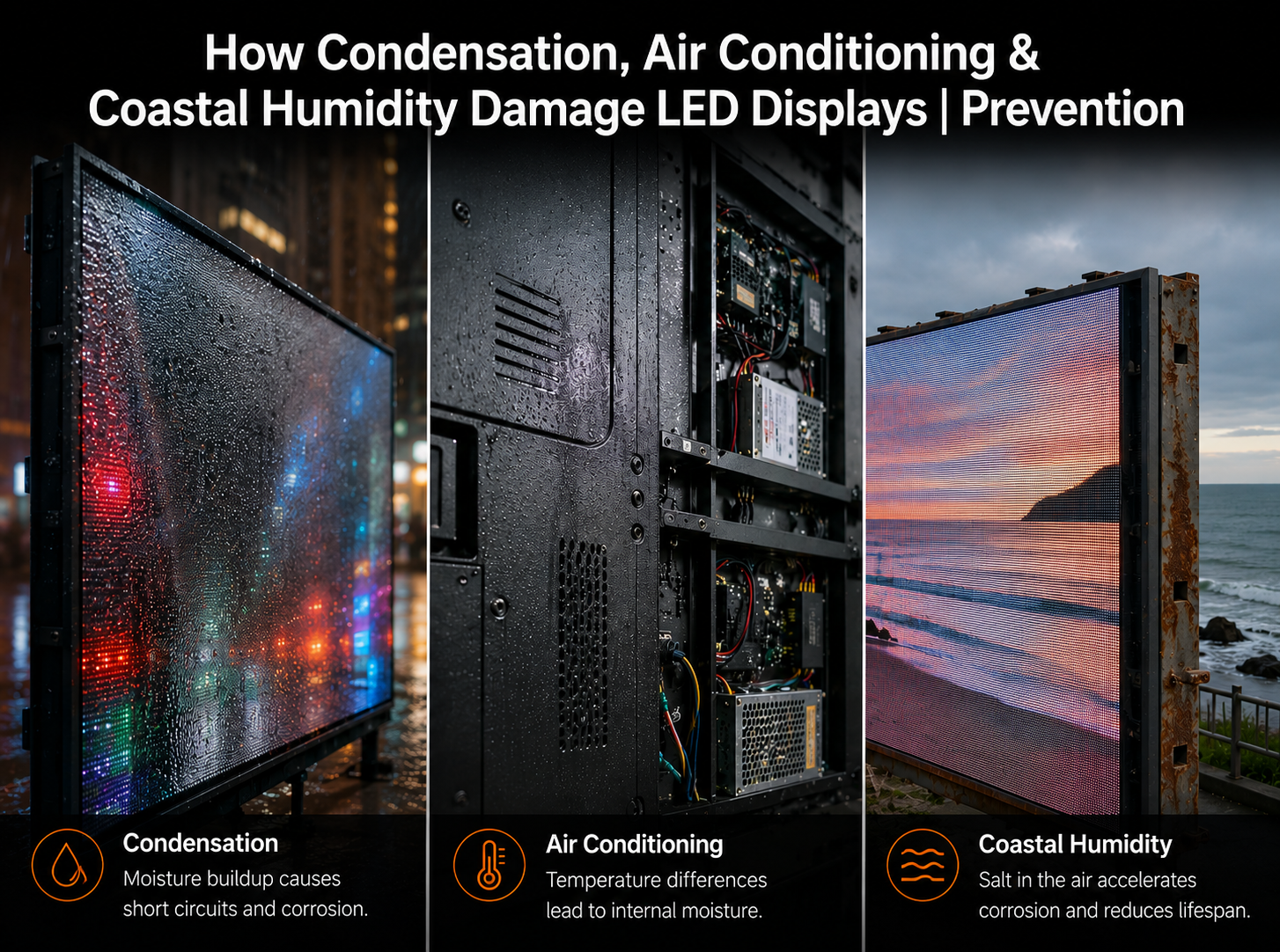
How Condensation, Air Conditioning & Coastal Humidity Damage LED Displays | Prevention Guide
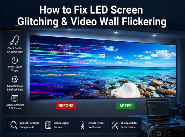
How to Fix LED Screen Glitching & Video Wall Flickering