
Table of Contents
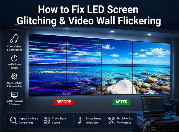
With the massive adoption of full-color LED displays across various industries, maintaining long-term display integrity has become a core focus for engineers and event directors alike. Over years of continuous operation, visual anomalies such as screen glitching, total blackouts, and localized pixel artifacts are bound to happen.
When an LED video wall experiences severe pixel noise or erratic flickering, on-site tech teams often panic. However, from a professional Pro-AV engineering perspective, most display failures boil down to two critical system elements: Power infrastructure and Signal connectivity. This technical guide breaks down the root causes of LED display glitches and outlines an industry-standard framework to troubleshoot them like a pro.
01 Understanding LED Screen Glitching
LED screen glitching—often manifested as horizontal lines, flashing blocks, scrambled pixels, or rapid refresh tearing—is rarely a random occurrence. It is the physical manifestation of either a voltage drop or data corruption occurring within the display matrix.
Because modern fine-pitch LED walls operate on high-frequency scanning rates and low-voltage DC currents, even a microscopic variance in power supply or a minor impedance shift in a data cable will cause a visible glitch. Diagnosing the issue systematically prevents minor cable contact failures from escalating into costly, unnecessary hardware replacements.
02 Top 3 Root Causes of LED Wall Failures
To run an efficient diagnosis, you must map out the three primary pain points where system stability fails: power distribution, signal transmission networks, and backend hardware configurations.
1. Power Supply Degradation ("Power Starvation")
Power instability is the number one driver behind heavy screen flickering and horizontal scrolling lines. This typically happens across two critical vectors:
- Insufficient PSU Wattage: If the integrated Power Supply Unit (PSU) capacity is overloaded, the modules at the tail end of the daisy chain suffer from voltage drop. Without dual-path power redundancy, this "starvation" corrupts the IC driving cycles, translating to severe image distortion.
- Voltage Fluctuations: Aging components, loose terminal screws, or high ambient humidity can cause significant DC output variations. If the voltage delta between different sections of the cabinet grid exceeds 0.5V, the mismatch induces constant pixel shaking.
2. Connectivity Failures in the "Nervous System"
Data ribbons and internal signal connections serve as the display's nervous system. Minor physical disruptions cause instant signal degradation:
- Oxidized or Loose Ribbon Cables: The internal flat ribbon cables connecting the hub board to the LED modules are highly susceptible to vibration, dust accumulation, and oxidation. This blocks the driving data streams, leading to localized, sharp-edged glitch blocks.
- Network Cable Interference & Degradation: For large-scale setups, poor RJ45 terminations or unshielded network cables running adjacent to heavy-duty power lines will suffer from Electromagnetic Interference (EMI). This causes random pixel noise and severe image stuttering.
- Signal Port Overload: Exceeding the maximum pixel loading capacity per receiving card output port will cause severe data attenuation and timing misalignment at the end of the signal run.
3. Configuration Corruptions & Hardware Malfunctions
When glitches are widespread yet clean-cut, the issue shifts from physical wiring to digital system integrity:
- Receiving Card Parameter Errors: Large-scale, chaotic image scrambling often indicates that the receiving card configuration file (.rcfgx) has been corrupted, or the scanning parameters don't match the current refresh rates.
- Driver IC or LED Bead Damage: If a specific, isolated module displays permanent solid color lines (known as "caterpillar defects"), it points to a physical short-circuit in the onboard driver IC pins or a punctured LED bead.
03 The Golden Troubleshooting Framework
Field engineers cannot afford to waste time guessing during a live event broadcast or critical command center operations. You must execute your diagnosis based on a structured, three-tiered framework:
- 1. Simple Before Complex Always start with non-destructive, quick actions. Re-plug critical connectors, power cycle the sending box, and check basic cabling before unscrewing chassis components or replacing expensive cards.
- 2. Software Before Hardware Verify that your video source resolution, GPU refresh rates, and sender card mapping are synchronized. Cross-test the feed using a backup laptop to immediately isolate media player faults before tearing into the hardware layout.
- 3. Power Before Signal Stable electrical delivery is the baseline of all visual logic. Use a digital multimeter to verify the 5V DC output stability across the hub board. If your power delivery is fluctuating, fixing data cables will not solve the issue.
04 Real-World Diagnostic Scenarios
Scenario A: Total Screen Blackout or Violent Full-Screen Flashing
Actionable Steps: Check your primary AC distribution box immediately. Measure if the 220V/110V main input line is steady. Ensure the main power relays aren't tripping due to sudden inrush current spikes. If the power input is sound, check the primary fiber/CAT6 cable connecting your master sending controller to the first cabinet link.
Scenario B: Sectional Failures (Garbled Rows, Half-Chassis Blackout, Split Screen)
Actionable Steps:
- Locate the first abnormal module in the chain and verify its dedicated PSU indicator light is a solid green.
- Inspect the internal cascade ribbon cables for oxidation or mechanical displacement. Clean the copper contact tabs thoroughly. Ensure signal lines are physically routed away from high-power line transformers to prevent heavy EMI contamination.
- Trace Output Circuits: Utilize a multimeter to check trace paths from the output ports to the signal buffer IC chips for short circuits. Verify clock latch signal continuity and test the cascade data link between the final driver IC and the hub connector interface.
Scenario C: Random Digital Noise and Shaking Pixels
Actionable Steps: Confirm whether the active controller configuration profile (.rcfgx) matches the current batch of cabinet modules. Ensure the receiving card shows a stable, flashing green status LED, indicating healthy data synchronization. Lastly, measure the local 5V DC output dedicated to the controller board to eliminate ripple voltage anomalies.
Scenario D: Media Server Thermal Overloading
Actionable Steps: Poor thermal venting within the processing rack causes the server's GPU core temperatures to skyrocket, outputting heavily glitched source feeds. Verify that all chassis fans are clear of dust debris, lubricate the cooling bearings if necessary, and optimize airflow to instantly drop core temperatures and clear up the video stream.
Conclusion: Systematically tracking display glitches back to their electrical, signal, or hardware source guarantees a fast resolution. For high-stakes commercial environments, investing in ruggedized hardware represents the ultimate insurance policy.
Discover how our ultra-durable, dual-IP65 protected PL Series LED Displays eliminate on-site vulnerabilities entirely. For additional configuration support, access our Download Center or contact our Pro-AV engineering support today!
Frequently Asked Questions
White images require maximum power draw from the PSUs. If your power supply configuration is underpowered or experiencing significant voltage drops, the screen will starve for electricity and start flashing violently under heavy loads.
If the glitch has clean, distinct geometric boundaries (e.g., exactly one module or one cabinet block is garbled), it is a physical ribbon or cable issue. Widespread, chaotic, or non-linear pixel tearing across the whole screen typically indicates a configuration file corruption.
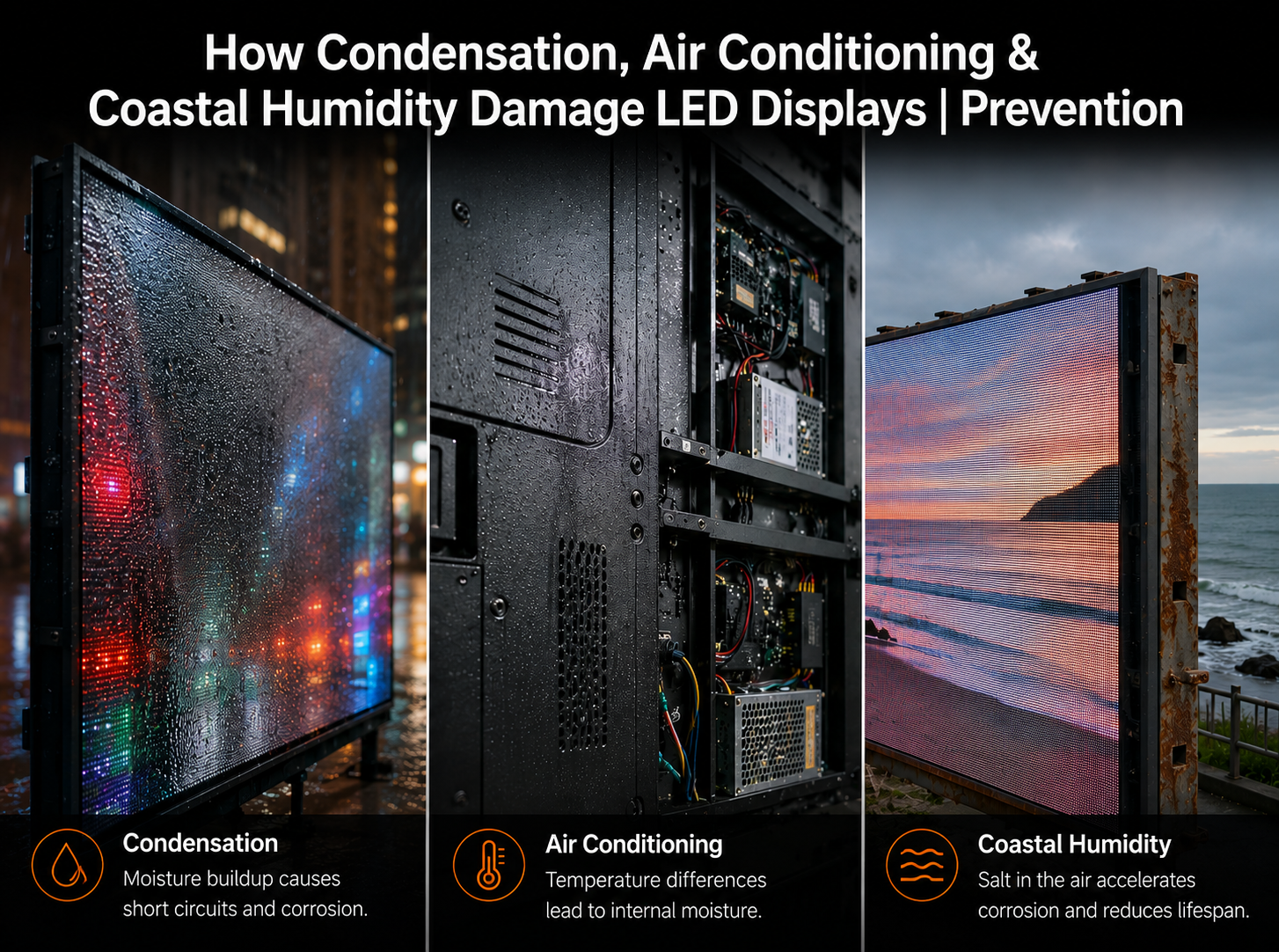
Yes. Moisture build-up degrades internal ribbon contacts and causes tiny electrical leakages across the PSU terminal outputs. Utilizing highly protected cabinets, such as the VMX magnesium-aluminum alloy frames with front/rear IP65 ratings, prevents environmental moisture from inducing these glitches.



Share:
LED Display Power Supply Guide: Prevent Hardware Failure & Surges
2026 Guide to Most Common Outdoor LED Screen Cabinet Types