
Table of Contents
01 Why Colour Distortion Happens | 02 Software & Settings | 03 Cable & Connection Faults | 04 Ambient Lighting | 05 Camera Colour Problems | 06 Hardware Failures | 07 LED Ageing & Calibration | 08 Full Diagnostic Process | ✓ Troubleshooting Checklist | FAQ
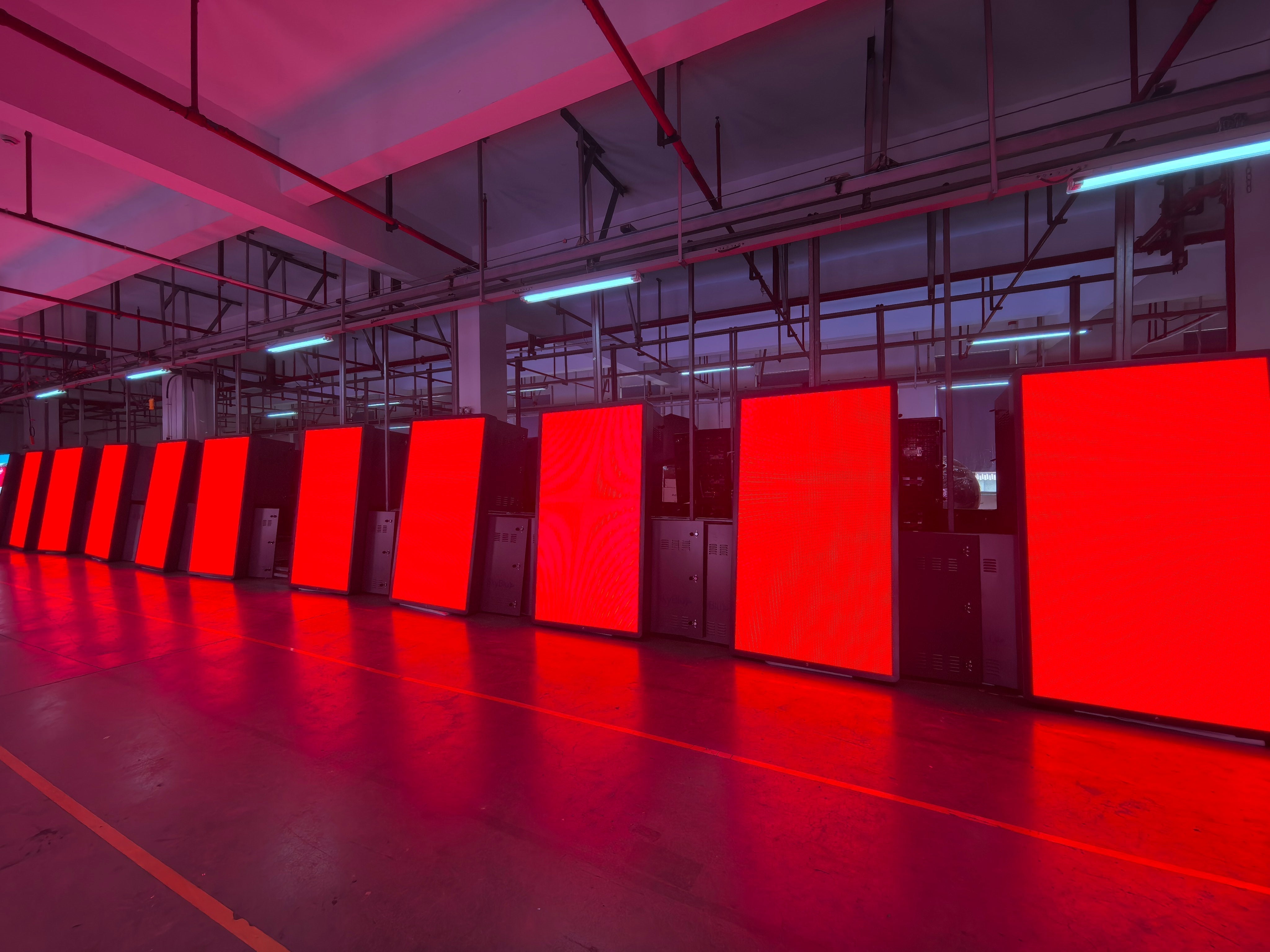
Your LED display looked perfect at installation. Now the colours look wrong — shifted, uneven, or completely inaccurate. Before calling a technician, understand this: LED display colour distortion has eight distinct causes, most of which can be diagnosed and resolved without any replacement parts. This guide works through every cause systematically, from the simplest fixes to hardware-level failures, so you can identify the exact problem and apply the right solution.
LED display colour distortion is one of the most frequently reported issues in commercial display operations — and one of the most frequently misdiagnosed. Operators assume hardware failure when the actual cause is a software misconfiguration. They replace panels when the problem is ambient lighting. They call technicians when a system restart would have resolved the issue in two minutes.
Understanding the full range of causes is the starting point for any effective diagnosis. LED display colour distortion falls into four categories:
- ▸System and software issues — incorrect RGB colour order, misconfigured white balance, wrong display mode settings, or control system configuration errors. These are the most common cause and the easiest to fix.
- ▸Connection and signal integrity issues — damaged, loose, or oxidised data cables, HDMI connections, or receiving card connectors causing signal corruption between the source and the display panels.
- ▸Environmental interference — ambient lighting that affects perceived colour, including colour temperature mismatch, uneven illumination, light reflections on the display surface, and electromagnetic interference from fluorescent fixtures.
- ▸Hardware failure and LED degradation — failed driver ICs, damaged receiving cards, individual LED chip failure, or long-term differential luminance degradation across the RGB channels.
The diagnostic process should always start with the simplest and most reversible causes before proceeding to hardware investigation. Replacing components is expensive and time-consuming. Most colour distortion issues are resolved at the software or environment level.
Before any investigation, perform a full system restart — power off both the display panels and the sending card, wait 30 seconds, then power back on in sequence: sending card first, then panels. A significant percentage of intermittent colour distortion issues resolve with a restart. If the problem disappears after a restart, monitor for recurrence before taking further action.
Software misconfiguration accounts for a large proportion of LED display colour distortion cases. The control software — NovaStar NovaLCT, Colorlight, or equivalent — contains multiple settings that directly affect colour output. An incorrect setting in any one of them can produce colour distortion that appears to be a hardware problem.
RGB colour order is the most common misconfiguration. LED displays are manufactured with a specific colour channel arrangement — the physical order in which red, green, and blue sub-pixels are wired to the driver IC. If the control software's RGB setting does not match the panel's physical wiring, colours will be transposed. Red content appears green, green appears blue, and so on. Check the colour order setting in the control software and verify it matches the panel manufacturer's specification.
White balance settings control the relative brightness of each colour channel. If the red, green, and blue channel brightness levels are not balanced correctly, the display will produce a colour cast across all content — too much green brightness produces a green cast, too much red produces a warm shift, and so on. Open the white balance or colour adjustment panel in the control software and verify that all three channels are set to the same baseline value, then recalibrate using a reference white point.
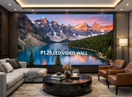
Display mode and gamma settings affect how brightness values in the source content are mapped to LED output levels. An incorrect gamma curve will compress or expand certain tonal ranges, causing colours in those ranges to appear incorrect. Verify that the display mode matches the content's colour space — sRGB for standard content, DCI-P3 for cinema and broadcast production environments.
- ▸Open NovaStar NovaLCT or your control software
- ▸Check Screen Settings → Colour Order → verify RGB sequence matches panel spec
- ▸Check White Balance → verify R/G/B channel values are equal at baseline
- ▸Check Display Mode → verify gamma curve and colour space match content requirements
- ▸If settings appear correct, reset all colour settings to factory defaults and reapply from scratch
Signal integrity between the sending card and the LED panels is essential for accurate colour reproduction. Any interruption or degradation of the data signal introduces errors that manifest as colour shifts, pixel dropout, or flickering colour across sections of the display.
The most common connection-related causes of colour distortion are:
- ▸Loose or partially seated connectors — Data cables between modules, HDMI connections from the source, and ribbon cables inside the cabinet can work loose over time, particularly in rental environments or installations subject to vibration. Disconnect all data cables, inspect the connector pins for damage or debris, and reseat firmly. For ribbon cables with oxidised contacts, clean gently with a pencil eraser before reseating.
- ▸Damaged or degraded data cables — Data cables that have been bent sharply, pinched, or exposed to physical stress can develop internal wire breaks that cause intermittent signal loss. The cable may appear intact externally but have a broken conductor inside. Swap the suspect cable with a known-good replacement to test.
- ▸Oxidised connector contacts — In humid environments or installations near coastal air, connector contacts oxidise over time, increasing contact resistance and degrading signal quality. Oxidised contacts often appear as brown or dark discolouration on the metal contact surface. Clean with appropriate contact cleaner or replace the connector if cleaning is insufficient.
- ▸Incorrect cable length or quality for signal distance — Data signals degrade over long cable runs. If the installation uses long cable runs without signal repeaters, or uses low-quality cables not rated for the run length, signal integrity errors can produce colour artefacts on the panels at the end of the data chain. Use signal repeaters for runs exceeding the cable type's rated distance.
Ambient lighting is the most consistently overlooked cause of perceived LED display colour distortion — and the most frequently misattributed to hardware failure. The display is producing accurate colour output, but the room lighting is altering how that colour appears to observers and to cameras.
Understanding how ambient lighting affects LED display colour perception requires understanding how human vision adapts to different light sources. The eye continuously adjusts its white point reference based on the dominant light in the environment. If the room lighting has a strong colour cast, the eye compensates — and any neutral surface in that environment, including an LED display showing white, appears to have the opposite cast.
Six specific ambient lighting conditions cause LED display colour distortion in commercial environments:
- ▸Low colour temperature lighting (below 3,500K) — Warm-white LEDs, halogen, or incandescent lighting creates a yellow-red ambient cast. The display appears to shift towards warm tones, and whites look yellowish or reddish. This is the most common ambient lighting cause of colour complaints in meeting rooms and hospitality environments. The fix is either changing the room lighting to neutral-white (5,000–6,500K) or recalibrating the display's white balance to compensate for the specific room lighting condition.
- ▸High contrast between display and room brightness — When the room is significantly darker than the display, human visual adaptation causes the display to appear to shift in colour as the eye attempts to balance the dominant light sources. Maintain consistent ambient lighting that complements the display brightness rather than creating extreme contrast.
- ▸Uneven room illumination — If ceiling lights create bright and dark zones across the display's viewing area, different parts of the display appear to have different colour casts depending on which zone the viewer is standing in. Ensure even, consistent ambient illumination across the entire viewing area.
- ▸Mixed colour temperature lighting — Using multiple light sources with different colour temperatures (e.g., warm-white downlights combined with cool-white strip lighting) creates inconsistent colour perception across the room. Different viewing positions see the display in different ambient light conditions, producing inconsistent colour evaluation.
- ▸Direct light reflection on the display surface — Light fixtures positioned at angles that create reflections on the LED panel surface effectively overlay the display content with a colour-shifted light layer. This is particularly common with glossy or matte-finish panels in rooms with low-angle ceiling lights. Reposition the light fixtures or install anti-glare diffusers to eliminate surface reflections.
- ▸Fluorescent lamp electromagnetic interference — Older fluorescent lighting generates electromagnetic fields that can interfere with LED driver IC electronics, causing intermittent colour errors or flickering. If the display is close to fluorescent fixtures, replace them with LED lighting or add electromagnetic shielding between the light source and the display cabinet.
A conference room LED display that appeared correct in the morning but looked progressively redder throughout the day was ultimately traced to the angle of direct sunlight entering through unshaded windows in the afternoon — not any display malfunction. The light was falling directly on the display surface, creating a warm reflection that progressively increased as the sun's angle changed. Installing window blinds resolved the issue entirely without any changes to the display hardware or software.
If the colour distortion only appears in photographs or video recordings of the display — and the display looks correct to the human eye — the problem is almost certainly not a display fault at all. It is a camera-display compatibility issue caused by a mismatch between the camera's shutter speed and the display's refresh rate.
LED displays operate by rapidly switching LEDs on and off at high speed (the refresh cycle). The human eye integrates this rapid flickering into a continuous image. A camera sensor, however, captures light over a fixed exposure period. If the camera's shutter speed is not synchronised with the display's refresh rate, the sensor captures the display at a point mid-cycle — where only some colour channels have completed their refresh. The result is colour banding, colour shifts, or flickering in the recorded image that does not exist on the display itself.
The solution depends on the application:
- ▸For general photography — Increase the display refresh rate to 3,840 Hz or above. At this refresh rate, the cycling speed is fast enough that most camera shutter speeds do not capture a mid-cycle frame. The image captured will match what the human eye sees.
- ▸For broadcast cameras — Broadcast cameras using shutter speeds at 1/50 or 1/60 require a minimum display refresh rate of 3,840 Hz. Cameras using higher shutter speeds require 7,680 Hz or above. Confirm the camera shutter speed range with the production team and specify the display refresh rate accordingly.
- ▸For XR studio and virtual production — Cinema cameras with variable shutter angles require 7,680 Hz minimum. Below this threshold, rolling shutter artefacts and colour channel banding appear in ICVFX compositing work and cannot be corrected in post-production.
If software settings are correct, connections are secure, and ambient lighting has been ruled out, the colour distortion is likely caused by a hardware failure. Hardware-level colour distortion typically manifests in a distinct and localised pattern — affecting a specific section of the display, a specific colour channel, or a specific panel — rather than the whole display uniformly.
- ▸Failed driver IC — The driver IC controls the current to individual LED sub-pixels. A partially failed driver IC will produce incorrect current to one or more colour channels, resulting in a colour cast or missing colour channel across the modules controlled by that IC. The affected area will be a distinct rectangular zone corresponding to the IC's coverage area. Driver IC replacement requires a technician with soldering capability.
- ▸Failed or damaged receiving card — The receiving card processes the data signal from the sending card and distributes it to the LED modules. A damaged receiving card can corrupt the colour data for all modules connected to it, producing a colour shift or complete loss of one colour channel across an entire cabinet or group of cabinets. Swap the receiving card with a spare to confirm the diagnosis — receiving card replacement is a straightforward plug-in swap that does not require soldering.
- ▸Individual LED chip failure — Individual LED chips fail over time, particularly in high-operating-hour installations. A single failed LED chip produces a dark or wrong-colour pixel. A cluster of failed chips in the same colour channel produces a visible tonal shift in that area of the display. If the number of failed chips is small (less than 0.1% of total pixel count), monitor without immediate replacement. If the count is increasing rapidly, it indicates accelerated degradation — typically caused by driver IC overdriving or thermal management failure — requiring further investigation.
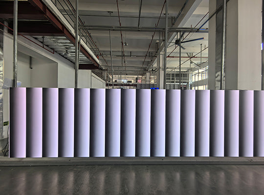
LED displays that have been in operation for several years will experience gradual colour shift as a normal consequence of differential LED degradation — not a hardware failure. Red, green, and blue LED chips degrade at different rates. Green LEDs typically maintain luminance longer than red or blue. As the imbalance between channels grows over time, the display's white balance drifts and colour accuracy deteriorates.
This is entirely expected behaviour and is managed through scheduled professional calibration:
- ▸Point-by-point calibration — Professional calibration measures the actual output of each pixel on the display and generates a correction map that compensates for the variation across the display surface. This correction is stored in the receiving cards and applied in real time to every pixel. Point-by-point calibration is performed using a calibration camera and measurement software (NovaStar MCCS, Colorlight, or third-party photometric tools). For commercial installations, calibration every 12–18 months is the recommended maintenance schedule.
- ▸Factory calibration at point of manufacture — All LED display modules leave the factory with small variations in individual LED chip brightness and colour characteristics. High-quality manufacturers perform per-module calibration at the factory and store correction data on the module's receiving card. Displays that were never factory-calibrated or had their calibration data lost will show visible brightness and colour non-uniformity from the point of installation.
- ▸Calibration degradation threshold — Calibration has a practical ceiling. If individual LED chips have degraded beyond a certain threshold relative to their neighbours, calibration can no longer compensate fully — the correction required would reduce the brighter pixels to such low output levels that overall brightness becomes unacceptably low. At this point, module replacement is the only solution. For high-quality LED chips, this threshold is typically reached after 8–12 years of operation.
Follow this sequence when diagnosing LED display colour distortion. Work through each step in order before proceeding to the next — this prevents unnecessary hardware replacement and identifies the root cause efficiently.
- ▸Step 1 — Restart Power off the display panels and sending card. Wait 30 seconds. Restart sending card first, then panels. Observe whether the colour distortion persists.
- ▸Step 2 — Check ambient lighting Switch off all room lights. Observe the display in darkness. If the colour distortion disappears or changes significantly without room lights, the ambient lighting environment is the cause — investigate room lighting colour temperature, evenness, and reflection angles.
- ▸Step 3 — Verify software settings Open the control software. Check RGB colour order, white balance channel values, display mode, and gamma settings. Reset to factory defaults if settings appear incorrect or unknown.
- ▸Step 4 — Inspect all connections Disconnect and reseat all data cables, HDMI connections, and ribbon cables. Inspect for damage, oxidation, or contamination. Replace any suspect cables.
- ▸Step 5 — Localise the hardware fault If the distortion is localised to specific panels or zones, swap the receiving card in the affected cabinet with a known-good spare. If the distortion moves with the receiving card, replace the card. If it stays with the cabinet, the fault is in the panel itself — driver IC or LED chip level.
- ▸Step 6 — Schedule professional calibration If no hardware fault is found but colour uniformity has deteriorated gradually over time, the cause is LED ageing. Schedule a point-by-point calibration using NovaStar MCCS or equivalent calibration software and a photometric measurement device.
Work through this checklist in order before calling a technician or ordering replacement parts:
- ✓ Full system restart performed (sending card + panels, 30 second pause)
- ✓ Display observed with all room lights switched off to isolate ambient lighting influence
- ✓ RGB colour order verified in control software against panel specification
- ✓ White balance R/G/B channel values confirmed equal at baseline
- ✓ All data cables disconnected, inspected, and reseated
- ✓ Connector contacts inspected for oxidation — cleaned or replaced as needed
- ✓ If distortion is localised: receiving card swap test performed to isolate receiving card vs panel fault
- ✓ If only visible on camera: display refresh rate confirmed at 3,840 Hz minimum — 7,680 Hz for broadcast/cinema cameras
- ✓ If colour shift is gradual and display has been in operation for 2+ years: professional point-by-point calibration scheduled
VMX Visual's LED display range ships with factory-level point-by-point calibration data on every receiving card, first-tier Nationstar LEDs for consistent colour across the full display surface, and NovaStar control system integration for precise on-site colour management. EU warehouse spare parts — including receiving cards, driver modules, and LED modules — available for 24–48 hour dispatch across Europe.
References & Standards
- NovaStar — LED display calibration methodology, NovaLCT software, and MCCS point-by-point calibration system
- International Electrotechnical Commission (IEC) — LED display photometric measurement and colour uniformity standards
- Colorlight — LED display control system colour calibration and white balance adjustment


Compartir:
The Hidden Cost of "Cheap" LED Displays: Power Consumption & Maintenance
Full Flip Chip COB LED Display Explained | COB vs SMD & Flip Chip Advantages