
Inhaltsverzeichnis
01 Warum Farbverzerrungen auftreten | 02 Software & Einstellungen | 03 Kabel- & Verbindungsfehler | 04 Umgebungsbeleuchtung | 05 Kamera-Farbprobleme | 06 Hardware-Ausfälle | 07 LED-Alterung & Kalibrierung | 08 Vollständiger Diagnoseprozess | ✓ Checkliste zur Fehlerbehebung | FAQ
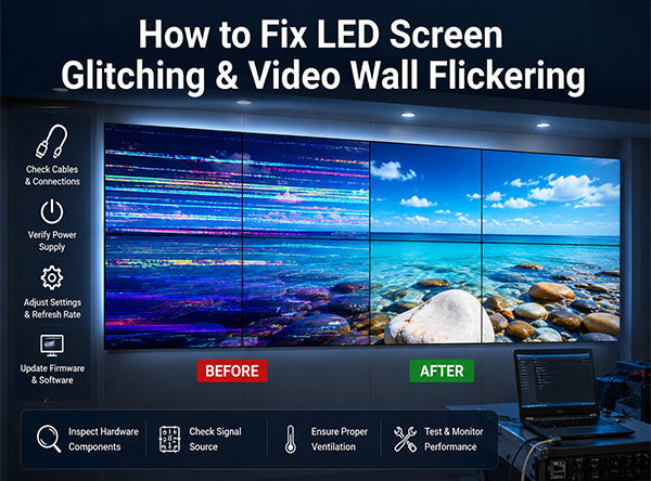
Ihr LED-Display sah bei der Installation perfekt aus. Jetzt sehen die Farben falsch aus – verschoben, ungleichmäßig oder völlig ungenau. Bevor Sie einen Techniker rufen, sollten Sie dies verstehen: Farbverzerrungen bei LED-Displays haben acht unterschiedliche Ursachen, von denen die meisten ohne Ersatzteile diagnostiziert und behoben werden können. Dieser Leitfaden behandelt systematisch jede Ursache, von den einfachsten Korrekturen bis zu Hardware-Ausfällen, damit Sie das genaue Problem identifizieren und die richtige Lösung anwenden können.
Farbverzerrungen bei LED-Displays sind eines der am häufigsten gemeldeten Probleme im kommerziellen Display-Betrieb – und eines der am häufigsten falsch diagnostizierten. Bediener gehen von Hardware-Ausfällen aus, obwohl die eigentliche Ursache eine Fehlkonfiguration der Software ist. Sie tauschen Panels aus, obwohl das Problem die Umgebungsbeleuchtung ist. Sie rufen Techniker, obwohl ein Systemneustart das Problem in zwei Minuten gelöst hätte.
Das Verständnis des gesamten Spektrums der Ursachen ist der Ausgangspunkt für jede effektive Diagnose. Farbverzerrungen bei LED-Displays fallen in vier Kategorien:
- ▸System- und Softwareprobleme – falsche RGB-Farbordnung, falsch konfigurierter Weißabgleich, falsche Anzeigemodus-Einstellungen oder Konfigurationsfehler des Steuerungssystems. Dies sind die häufigsten Ursachen und am einfachsten zu beheben.
- ▸Probleme mit der Verbindung und Signalintegrität – beschädigte, lose oder oxidierte Datenkabel, HDMI-Verbindungen oder Empfängerkartenanschlüsse, die zu einer Signalstörung zwischen der Quelle und den Anzeigetafeln führen.
- ▸Umweltstörungen – Umgebungsbeleuchtung, die die wahrgenommene Farbe beeinflusst, einschließlich Farbtemperatur-Fehlpassung, ungleichmäßige Beleuchtung, Lichtreflexionen auf der Displayoberfläche und elektromagnetische Störungen durch Leuchtstoffröhren.
- ▸Hardware-Ausfall und LED-Degradation – ausgefallene Treiber-ICs, beschädigte Empfängerkarten, Ausfall einzelner LED-Chips oder langfristige differentielle Luminanzdegradation über die RGB-Kanäle.
Der Diagnoseprozess sollte immer mit den einfachsten und reversibelsten Ursachen beginnen, bevor eine Hardwareuntersuchung durchgeführt wird. Der Austausch von Komponenten ist teuer und zeitaufwendig. Die meisten Probleme mit Farbverzerrungen werden auf Software- oder Umgebungsebene behoben.
Führen Sie vor jeder Untersuchung einen vollständigen Systemneustart durch – schalten Sie sowohl die Anzeigetafeln als auch die Sendekarte aus, warten Sie 30 Sekunden und schalten Sie sie dann nacheinander wieder ein: zuerst die Sendekarte, dann die Anzeigetafeln. Ein erheblicher Prozentsatz intermittierender Farbverzerrungen wird durch einen Neustart behoben. Wenn das Problem nach einem Neustart verschwindet, überwachen Sie das Wiederauftreten, bevor Sie weitere Maßnahmen ergreifen.
Software-Fehlkonfigurationen machen einen Großteil der Fälle von Farbverzerrungen bei LED-Displays aus. Die Steuerungssoftware – NovaStar NovaLCT, Colorlight oder Äquivalente – enthält mehrere Einstellungen, die die Farbausgabe direkt beeinflussen. Eine falsche Einstellung in einer davon kann Farbverzerrungen verursachen, die als Hardwareproblem erscheinen.
Die RGB-Farbordnung ist die häufigste Fehlkonfiguration. LED-Displays werden mit einer spezifischen Farbkanalanordnung hergestellt – der physischen Reihenfolge, in der rote, grüne und blaue Subpixel mit dem Treiber-IC verbunden sind. Wenn die RGB-Einstellung der Steuerungssoftware nicht mit der physischen Verkabelung des Panels übereinstimmt, werden Farben transponiert. Rote Inhalte erscheinen grün, grüne erscheinen blau und so weiter. Überprüfen Sie die Farbreihenfolge in der Steuerungssoftware und stellen Sie sicher, dass sie mit den Spezifikationen des Panelherstellers übereinstimmt.
Die Weißabgleichseinstellungen steuern die relative Helligkeit jedes Farbkanals. Wenn die Helligkeitsstufen der roten, grünen und blauen Kanäle nicht korrekt ausgeglichen sind, erzeugt das Display einen Farbstich über alle Inhalte hinweg – zu viel grüne Helligkeit erzeugt einen Grünstich, zu viel Rot erzeugt eine warme Verschiebung und so weiter. Öffnen Sie das Weißabgleichs- oder Farbanpassungsfenster in der Steuerungssoftware und stellen Sie sicher, dass alle drei Kanäle auf denselben Basiswert eingestellt sind, und kalibrieren Sie dann mit einem Referenz-Weißpunkt neu.
Die Anzeigemodus- und Gamma-Einstellungen beeinflussen, wie Helligkeitswerte im Quellinhalt auf die LED-Ausgabepegel abgebildet werden. Eine falsche Gammakurve komprimiert oder erweitert bestimmte Tonwertebereiche, wodurch Farben in diesen Bereichen falsch erscheinen. Stellen Sie sicher, dass der Anzeigemodus dem Farbraum des Inhalts entspricht – sRGB für Standardinhalte, DCI-P3 für Kino- und Rundfunkproduktionsumgebungen.
- ▸Öffnen Sie NovaStar NovaLCT oder Ihre Steuerungssoftware
- ▸Überprüfen Sie Bildschirmeinstellungen → Farbreihenfolge → stellen Sie sicher, dass die RGB-Sequenz mit der Panelspezifikation übereinstimmt
- ▸Überprüfen Sie Weißabgleich → stellen Sie sicher, dass die R/G/B-Kanalwerte bei Baseline gleich sind
- ▸Überprüfen Sie den Anzeigemodus → stellen Sie sicher, dass die Gammakurve und der Farbraum den Inhaltsanforderungen entsprechen
- ▸Wenn die Einstellungen korrekt erscheinen, setzen Sie alle Farbeinstellungen auf die Werkseinstellungen zurück und wenden Sie sie von Grund auf neu an
Die Signalintegrität zwischen der Sendekarte und den LED-Panels ist für eine genaue Farbwiedergabe unerlässlich. Jede Unterbrechung oder Verschlechterung des Datensignals führt zu Fehlern, die sich als Farbverschiebungen, Pixelausfälle oder flackernde Farben in Abschnitten des Displays manifestieren.
Die häufigsten verbindungsbedingten Ursachen für Farbverzerrungen sind:
- ▸Lose oder teilweise sitzende Anschlüsse – Datenkabel zwischen Modulen, HDMI-Verbindungen von der Quelle und Flachbandkabel im Gehäuse können sich mit der Zeit lösen, insbesondere in Mietumgebungen oder bei Installationen, die Vibrationen ausgesetzt sind. Trennen Sie alle Datenkabel, überprüfen Sie die Anschlussstifte auf Beschädigungen oder Verunreinigungen und setzen Sie sie fest wieder ein. Bei Flachbandkabeln mit oxidierten Kontakten reinigen Sie diese vorsichtig mit einem Radiergummi, bevor Sie sie wieder einsetzen.
- ▸Beschädigte oder verschlechterte Datenkabel – Datenkabel, die stark gebogen, eingeklemmt oder physischem Stress ausgesetzt waren, können innere Drahtbrüche entwickeln, die zu intermittentem Signalverlust führen. Das Kabel kann äußerlich intakt erscheinen, aber einen gebrochenen Leiter im Inneren haben. Tauschen Sie das verdächtige Kabel gegen ein bekanntermaßen gutes Ersatzkabel aus, um es zu testen.
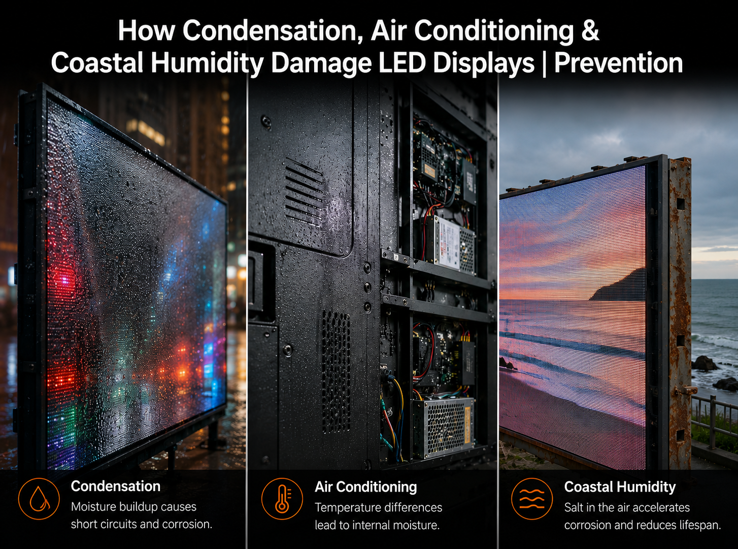
- ▸Oxidierte Anschlusskontakte – In feuchten Umgebungen oder Installationen in Küstennähe oxidieren die Anschlusskontakte mit der Zeit, wodurch der Kontaktwiderstand erhöht und die Signalqualität verschlechtert wird. Oxidierte Kontakte erscheinen oft als braune oder dunkle Verfärbung auf der Metallkontaktfläche. Reinigen Sie sie mit einem geeigneten Kontaktreiniger oder ersetzen Sie den Stecker, wenn die Reinigung nicht ausreicht.
- ▸Falsche Kabellänge oder -qualität für die Signalentfernung – Datensignale verschlechtern sich über lange Kabelstrecken. Wenn die Installation lange Kabelstrecken ohne Signalverstärker verwendet oder minderwertige Kabel verwendet, die nicht für die Lauflänge ausgelegt sind, können Signalintegritätsfehler Farbartfakte auf den Panels am Ende der Datenkette erzeugen. Verwenden Sie Signalverstärker für Strecken, die die Nennentfernung des Kabeltyps überschreiten.
Die Umgebungsbeleuchtung ist die am häufigsten übersehene Ursache für wahrgenommene Farbverzerrungen bei LED-Displays – und die am häufigsten fälschlicherweise der Hardware zugeschrieben wird. Das Display erzeugt eine genaue Farbausgabe, aber die Raumbeleuchtung verändert, wie diese Farbe von Betrachtern und Kameras wahrgenommen wird.
Um zu verstehen, wie die Umgebungsbeleuchtung die Farbwahrnehmung von LED-Displays beeinflusst, muss man verstehen, wie sich das menschliche Sehvermögen an verschiedene Lichtquellen anpasst. Das Auge passt seinen Weißpunktreferenz kontinuierlich an das vorherrschende Licht in der Umgebung an. Wenn die Raumbeleuchtung einen starken Farbstich aufweist, kompensiert das Auge – und jede neutrale Oberfläche in dieser Umgebung, einschließlich eines LED-Displays, das Weiß zeigt, scheint den entgegengesetzten Stich zu haben.
Sechs spezifische Umgebungslichtbedingungen verursachen Farbverzerrungen bei LED-Displays in kommerziellen Umgebungen:
- ▸Beleuchtung mit niedriger Farbtemperatur (unter 3.500 K) – Warmweiße LEDs, Halogen- oder Glühlampenbeleuchtung erzeugt einen gelb-roten Umgebungsstich. Das Display scheint sich zu warmen Tönen zu verschieben, und Weißtöne sehen gelblich oder rötlich aus. Dies ist die häufigste Ursache für Farbprobleme in Besprechungsräumen und im Gastgewerbe, die durch die Umgebungsbeleuchtung verursacht werden. Die Lösung besteht entweder darin, die Raumbeleuchtung auf Neutralweiß (5.000–6.500 K) umzustellen oder den Weißabgleich des Displays neu zu kalibrieren, um die spezifischen Raumlichtverhältnisse zu kompensieren.
- ▸Hoher Kontrast zwischen Display- und Raumhelligkeit – Wenn der Raum deutlich dunkler als das Display ist, führt die visuelle Anpassung des Menschen dazu, dass das Display in der Farbe verschoben erscheint, da das Auge versucht, die dominanten Lichtquellen auszugleichen. Sorgen Sie für eine konsistente Umgebungsbeleuchtung, die die Displayhelligkeit ergänzt, anstatt extreme Kontraste zu erzeugen.
- ▸Ungleichmäßige Raumbeleuchtung – Wenn Deckenleuchten helle und dunkle Zonen im Betrachtungsbereich des Displays erzeugen, erscheinen verschiedene Teile des Displays je nach Standpunkt des Betrachters mit unterschiedlichen Farbstichen. Sorgen Sie für eine gleichmäßige und konsistente Umgebungsbeleuchtung im gesamten Betrachtungsbereich.
- ▸Beleuchtung mit gemischter Farbtemperatur – Die Verwendung mehrerer Lichtquellen mit unterschiedlichen Farbtemperaturen (z. B. warmweiße Downlights kombiniert mit kaltweißen Lichtleisten) führt zu einer inkonsistenten Farbwahrnehmung im Raum. Unterschiedliche Betrachtungspositionen sehen das Display unter unterschiedlichen Umgebungslichtbedingungen, was zu einer inkonsistenten Farbbewertung führt.
- ▸Direkte Lichtreflexion auf der Displayoberfläche – Leuchten, die in Winkeln positioniert sind, die Reflexionen auf der Oberfläche des LED-Panels erzeugen, überlagern den Displayinhalt effektiv mit einer farbverschobenen Lichtschicht. Dies ist besonders häufig bei glänzenden oder mattierten Panels in Räumen mit niedrigwinkligen Deckenleuchten der Fall. Positionieren Sie die Leuchten neu oder installieren Sie entspiegelte Diffusoren, um Oberflächenreflexionen zu eliminieren.
- ▸Elektromagnetische Störungen durch Leuchtstofflampen – Ältere Leuchtstofflampen erzeugen elektromagnetische Felder, die die Elektronik der LED-Treiber-ICs stören können, was zu intermittierenden Farbfehlern oder Flackern führen kann. Wenn das Display in der Nähe von Leuchtstofflampen installiert ist, ersetzen Sie diese durch LED-Beleuchtung oder bringen Sie eine elektromagnetische Abschirmung zwischen der Lichtquelle und dem Displaygehäuse an.
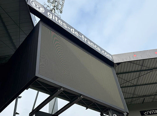
Ein LED-Display in einem Konferenzraum, das morgens korrekt aussah, aber im Laufe des Tages immer röter wurde, konnte schließlich auf den Winkel des direkten Sonnenlichts zurückgeführt werden, das am Nachmittag durch unbeschattete Fenster einfiel – und nicht auf eine Fehlfunktion des Displays. Das Licht fiel direkt auf die Displayoberfläche und erzeugte eine warme Reflexion, die mit der Änderung des Sonnenwinkels zunahm. Die Installation von Jalousien löste das Problem vollständig, ohne dass Änderungen an der Hardware oder Software des Displays vorgenommen werden mussten.
Wenn die Farbverzerrung nur auf Fotos oder Videoaufnahmen des Displays erscheint – und das Display für das menschliche Auge korrekt aussieht – ist das Problem mit ziemlicher Sicherheit kein Displayfehler. Es handelt sich um ein Kompatibilitätsproblem zwischen Kamera und Display, das durch eine Nichtübereinstimmung der Verschlusszeit der Kamera und der Bildwiederholfrequenz des Displays verursacht wird.
LED-Displays funktionieren, indem sie LEDs schnell ein- und ausschalten (der Refresh-Zyklus). Das menschliche Auge integriert dieses schnelle Flackern zu einem kontinuierlichen Bild. Ein Kamerasensor erfasst jedoch Licht über eine feste Belichtungszeit. Wenn die Verschlusszeit der Kamera nicht mit der Bildwiederholfrequenz des Displays synchronisiert ist, erfasst der Sensor das Display in der Mitte eines Zyklus – wo nur einige Farbkanäle ihren Refresh abgeschlossen haben. Das Ergebnis sind Farbbänder, Farbverschiebungen oder Flackern im aufgenommenen Bild, die auf dem Display selbst nicht vorhanden sind.
Die Lösung hängt von der Anwendung ab:
- ▸Für allgemeine Fotografie – Erhöhen Sie die Bildwiederholfrequenz des Displays auf 3.840 Hz oder mehr. Bei dieser Bildwiederholfrequenz ist die Zyklusgeschwindigkeit schnell genug, dass die meisten Kameraverschlusszeiten keinen Halbzyklus-Frame erfassen. Das aufgenommene Bild entspricht dem, was das menschliche Auge sieht.
- ▸Für Broadcast-Kameras – Broadcast-Kameras, die Verschlusszeiten von 1/50 oder 1/60 verwenden, erfordern eine minimale Bildwiederholfrequenz des Displays von 3.840 Hz. Kameras, die höhere Verschlusszeiten verwenden, erfordern 7.680 Hz oder mehr. Bestätigen Sie den Bereich der Kameraverschlusszeit mit dem Produktionsteam und legen Sie die Bildwiederholfrequenz des Displays entsprechend fest.
- ▸Für XR-Studio und virtuelle Produktion – Kinokameras mit variablen Shutter-Winkeln erfordern mindestens 7.680 Hz. Unterhalb dieses Schwellenwerts treten Rolling-Shutter-Artefakte und Farbkanal-Banding in der ICVFX-Kompositionsarbeit auf und können in der Postproduktion nicht korrigiert werden.
Wenn die Softwareeinstellungen korrekt sind, die Verbindungen sicher sind und Umgebungslicht ausgeschlossen wurde, wird die Farbverzerrung wahrscheinlich durch einen Hardwarefehler verursacht. Farbverzerrungen auf Hardwareebene äußern sich typischerweise in einem deutlichen und lokalisierten Muster – sie betreffen einen bestimmten Bereich des Displays, einen bestimmten Farbkanal oder ein bestimmtes Panel – und nicht das gesamte Display gleichmäßig.
- ▸Fehlerhafter Treiber-IC – Der Treiber-IC steuert den Strom zu einzelnen LED-Subpixeln. Ein teilweise fehlerhafter Treiber-IC erzeugt einen falschen Strom für einen oder mehrere Farbkanäle, was zu einem Farbstich oder einem fehlenden Farbkanal in den Modulen führt, die von diesem IC gesteuert werden. Der betroffene Bereich ist eine deutliche rechteckige Zone, die dem Abdeckungsbereich des ICs entspricht. Der Austausch des Treiber-ICs erfordert einen Techniker mit Lötkenntnissen.
- ▸Fehlerhafte oder beschädigte Empfängerkarte – Die Empfängerkarte verarbeitet das Datensignal der Sendekarte und verteilt es an die LED-Module. Eine beschädigte Empfängerkarte kann die Farbdaten für alle daran angeschlossenen Module beschädigen, was zu einer Farbverschiebung oder einem vollständigen Verlust eines Farbkanals in einem gesamten Gehäuse oder einer Gruppe von Gehäusen führt. Tauschen Sie die Empfängerkarte mit einem Ersatzteil aus, um die Diagnose zu bestätigen – der Austausch der Empfängerkarte ist ein einfacher Plug-in-Tausch, der kein Löten erfordert.
- ▸Ausfall einzelner LED-Chips – Einzelne LED-Chips fallen im Laufe der Zeit aus, insbesondere bei Installationen mit hohen Betriebsstunden. Ein einzelner ausgefallener LED-Chip erzeugt einen dunklen oder falschfarbigen Pixel. Eine Ansammlung ausgefallener Chips im selben Farbkanal erzeugt eine sichtbare Farbtonverschiebung in diesem Bereich des Displays. Wenn die Anzahl der ausgefallenen Chips gering ist (weniger als 0,1 % der gesamten Pixelanzahl), überwachen Sie diese ohne sofortigen Austausch. Wenn die Anzahl schnell zunimmt, deutet dies auf eine beschleunigte Degradation hin – typischerweise verursacht durch Übersteuerung des Treiber-ICs oder einen Fehler im Wärmemanagement – was weitere Untersuchungen erfordert.
LED-Displays, die mehrere Jahre in Betrieb waren, erfahren eine allmähliche Farbverschiebung als normale Folge der differenziellen LED-Degradation – keine Hardwarefehler. Rote, grüne und blaue LED-Chips degradieren unterschiedlich schnell. Grüne LEDs behalten typischerweise ihre Leuchtdichte länger als rote oder blaue. Da das Ungleichgewicht zwischen den Kanälen im Laufe der Zeit zunimmt, verschiebt sich der Weißabgleich des Displays und die Farbgenauigkeit verschlechtert sich.
Dies ist ein völlig erwartetes Verhalten und wird durch eine geplante professionelle Kalibrierung verwaltet:
- ▸Punkt-zu-Punkt-Kalibrierung – Bei der professionellen Kalibrierung wird die tatsächliche Ausgabe jedes Pixels auf dem Display gemessen und eine Korrekturkarte erstellt, die die Variationen auf der Displayoberfläche kompensiert. Diese Korrektur wird in den Empfängerkarten gespeichert und in Echtzeit auf jedes Pixel angewendet. Die Punkt-zu-Punkt-Kalibrierung wird mit einer Kalibrierungskamera und Messsoftware (NovaStar MCCS, Colorlight oder Photometrie-Tools von Drittanbietern) durchgeführt. Für kommerzielle Installationen wird eine Kalibrierung alle 12–18 Monate als empfohlener Wartungsplan empfohlen.
- ▸Werkskalibrierung zum Zeitpunkt der Herstellung – Alle LED-Displaymodule verlassen das Werk mit geringen Abweichungen in der Helligkeit und den Farbeigenschaften der einzelnen LED-Chips. Hochwertige Hersteller führen eine pro-Modul-Kalibrierung im Werk durch und speichern die Korrekturdaten auf der Empfängerkarte des Moduls. Displays, die nie werkskalibriert wurden oder deren Kalibrierungsdaten verloren gegangen sind, weisen ab dem Zeitpunkt der Installation sichtbare Helligkeits- und Farbungleichmäßigkeiten auf.
- ▸Kalibrierungs-Degradationsschwelle – Die Kalibrierung hat eine praktische Obergrenze. Wenn einzelne LED-Chips über einen bestimmten Schwellenwert hinaus im Verhältnis zu ihren Nachbarn degradiert sind, kann die Kalibrierung nicht mehr vollständig kompensieren – die erforderliche Korrektur würde die helleren Pixel auf so niedrige Ausgangswerte reduzieren, dass die Gesamthelligkeit unannehmbar niedrig wird. An diesem Punkt ist der Modulaustausch die einzige Lösung. Für hochwertige LED-Chips wird dieser Schwellenwert typischerweise nach 8–12 Betriebsjahren erreicht.
Befolgen Sie diese Reihenfolge bei der Diagnose von Farbverzerrungen bei LED-Displays. Arbeiten Sie jeden Schritt der Reihe nach ab, bevor Sie mit dem nächsten fortfahren – dies verhindert unnötigen Hardwareaustausch und identifiziert die Grundursache effizient.
- ▸Schritt 1 – Neustart Schalten Sie die Display-Panels und die Sendekarte aus. Warten Sie 30 Sekunden. Starten Sie zuerst die Sendekarte, dann die Panels. Beobachten Sie, ob die Farbverzerrung bestehen bleibt.
- ▸Schritt 2 – Umgebungsbeleuchtung prüfen Schalten Sie alle Raumlichter aus. Beobachten Sie das Display in der Dunkelheit. Wenn die Farbverzerrung ohne Raumlicht verschwindet oder sich signifikant ändert, ist die Umgebungsbeleuchtung die Ursache – untersuchen Sie die Farbtemperatur der Raumbeleuchtung, die Gleichmäßigkeit und die Reflexionswinkel.
- ▸Schritt 3 – Softwareeinstellungen überprüfen Öffnen Sie die Steuerungssoftware. Überprüfen Sie die RGB-Farbreihenfolge, die Weißabgleich-Kanalwerte, den Anzeigemodus und die Gamma-Einstellungen. Setzen Sie die Einstellungen auf die Werkseinstellungen zurück, wenn sie falsch oder unbekannt erscheinen.
- ▸Schritt 4 – Alle Verbindungen überprüfen Trennen und verbinden Sie alle Datenkabel, HDMI-Verbindungen und Flachbandkabel neu. Überprüfen Sie sie auf Beschädigungen, Oxidation oder Verunreinigungen. Ersetzen Sie alle verdächtigen Kabel.
- ▸Schritt 5 – Hardwarefehler lokalisieren Wenn die Verzerrung auf bestimmte Panels oder Zonen beschränkt ist, tauschen Sie die Empfängerkarte im betroffenen Gehäuse gegen ein bekanntermaßen funktionierendes Ersatzteil aus. Wenn sich die Verzerrung mit der Empfängerkarte verschiebt, ersetzen Sie die Karte. Wenn sie beim Gehäuse bleibt, liegt der Fehler im Panel selbst – auf der Ebene des Treiber-ICs oder des LED-Chips.
- ▸Schritt 6 – Professionelle Kalibrierung planen Wenn kein Hardwarefehler festgestellt wird, aber die Farbgleichmäßigkeit im Laufe der Zeit allmählich abgenommen hat, ist die Ursache die LED-Alterung. Planen Sie eine Punkt-zu-Punkt-Kalibrierung mit NovaStar MCCS oder einer gleichwertigen Kalibrierungssoftware und einem photometrischen Messgerät.
Arbeiten Sie diese Checkliste der Reihe nach ab, bevor Sie einen Techniker rufen oder Ersatzteile bestellen:
- ✓ Vollständiger Systemneustart durchgeführt (Sendekarte + Panels, 30 Sekunden Pause)
- ✓ Display bei ausgeschalteter Raumbeleuchtung beobachtet, um den Einfluss des Umgebungslichts zu isolieren
- ✓ RGB-Farbreihenfolge in der Steuerungssoftware gemäß Panelspezifikation überprüft
- ✓ Weißabgleich R/G/B-Kanalwerte bei Basislinie als gleich bestätigt
- ✓ Alle Datenkabel getrennt, geprüft und wieder angeschlossen
- ✓ Steckerkontakte auf Oxidation geprüft – bei Bedarf gereinigt oder ersetzt
- ✓ Wenn die Verzerrung lokal begrenzt ist: Empfängerkarte-Tauschtest durchgeführt, um Empfängerkarte von Panel-Fehler zu isolieren
- ✓ Wenn nur auf Kamera sichtbar: Display-Bildwiederholrate bestätigt mit mindestens 3.840 Hz – 7.680 Hz für Broadcast-/Kino-Kameras
- ✓ Wenn der Farbstich allmählich auftritt und das Display seit über 2 Jahren in Betrieb ist: Professionelle punktweise Kalibrierung geplant
Die LED-Display-Reihe von VMX Visual wird mit werkseitigen punktweisen Kalibrierungsdaten auf jeder Empfangskarte, erstklassigen Nationstar-LEDs für konsistente Farben auf der gesamten Displayoberfläche und NovaStar-Steuerungssystemintegration für präzises Farbmanagement vor Ort geliefert. Ersatzteile für das EU-Lager – einschließlich Empfangskarten, Treibermodule und LED-Module – sind für den Versand innerhalb von 24–48 Stunden in ganz Europa verfügbar.
Referenzen & Standards
- NovaStar – LED-Display-Kalibrierungsmethodik, NovaLCT-Software und MCCS Punkt-zu-Punkt-Kalibrierungssystem
- International Electrotechnical Commission (IEC) – Photometrische Messungen von LED-Displays und Standards für Farbgleichmäßigkeit
- Colorlight – Farbkalibrierung und Weißabgleichseinstellung von LED-Display-Steuerungssystemen


Teilen:
Die versteckten Kosten von „billigen“ LED-Displays: Stromverbrauch und Wartung
Full Flip Chip COB LED Display erklärt | COB vs. SMD & Flip Chip Vorteile