Inhaltsverzeichnis
01 Warum die Umwelt LED-Bildschirme beschädigt | 02 Direkter Luftzug durch Klimaanlage | 03 Kondensation in Stahlkonstruktionen | 04 Flüssigkeitsschäden in KTVs & Veranstaltungsorten | 05 Innenliegender Wasservorhang-Effekt | 06 Statische Elektrizität in trockenen Bereichen | 07 Küstenfeuchtigkeit & Salznebel | 08 Checkliste zur Prävention | FAQ
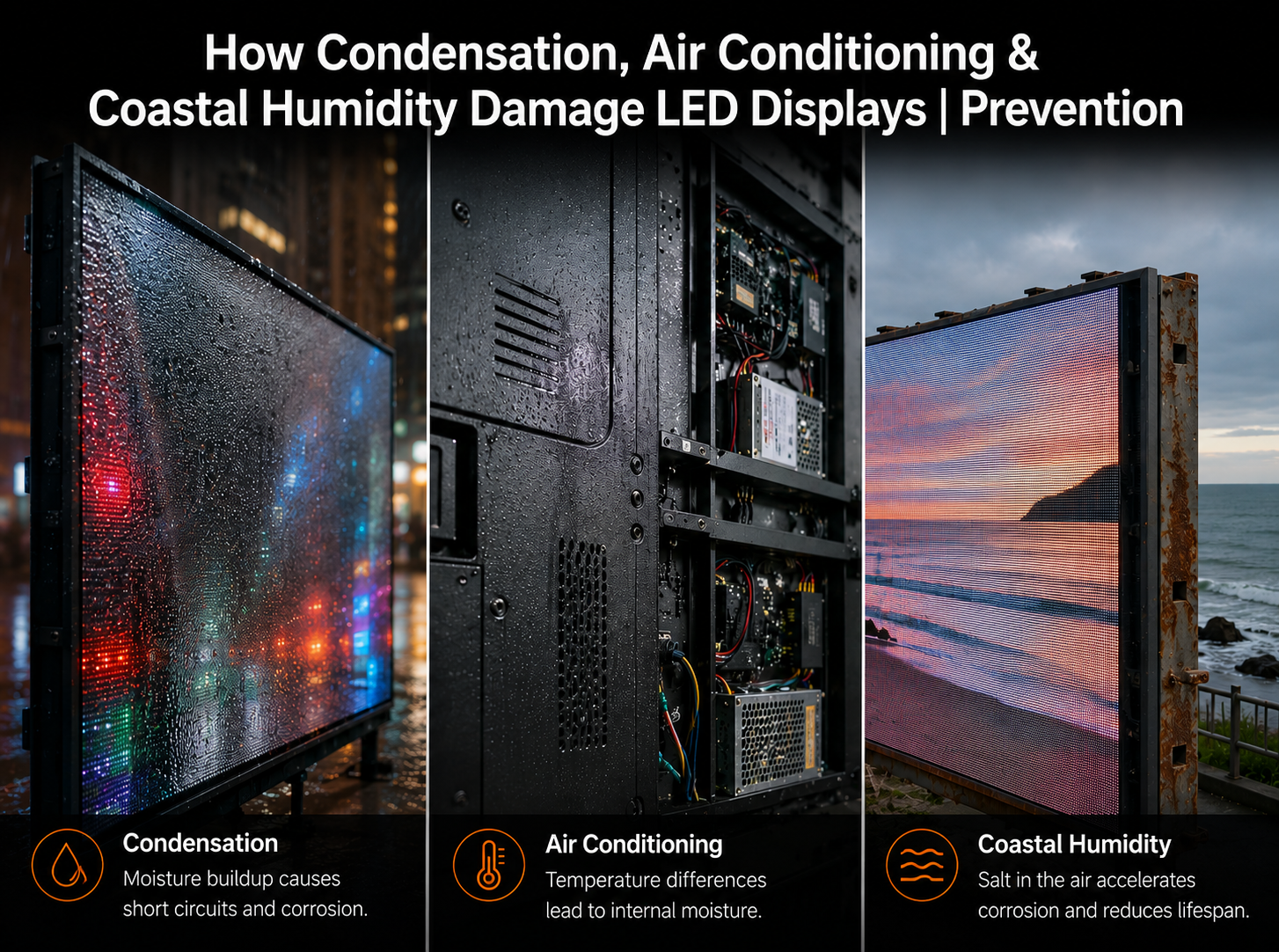
LED-Displays werden heute häufig in Konferenzräumen, Einzelhandelsflächen, KTV-Veranstaltungsorten, Stahlbaufabriken, für Küstenwerbung im Freien, in Kontrollräumen und Geschäftsgebäuden eingesetzt. Doch in realen Projekten rührt nicht jeder Ausfall von schlechter Produktqualität oder Hardwaredefekten her. Viele wiederkehrende Probleme – tote Pixel, „Raupen“-Leuchtlinien, Kurzschlüsse, Modulverbrennungen, Netzteilausfälle, Empfängerkartenschäden, Korrosion und anormale Helligkeit – stehen in direktem Zusammenhang mit der Betriebsumgebung. Klimaanlagen, Kondensation, hohe Luftfeuchtigkeit, Salznebel, leitfähige Flüssigkeiten, statische Elektrizität und schlechte Erdung können LED-Bildschirme beschädigen, wenn sie bei Design, Installation und Wartung nicht berücksichtigt werden. Dieser Artikel erläutert reale Fehlerfälle und bietet praktische Präventionsmethoden für LED-Display-Projekte in feuchten, küstennahen, trockenen und temperaturfluktuierenden Umgebungen.
Wenn ein LED-Display ausfällt, wird in der Regel zuerst die Schuld bei den LED-Modulen, Empfängerkarten, Treiber-ICs, Netzteilen oder der Lötqualität gesucht. In vielen tatsächlichen Servicefällen liegt die eigentliche Ursache jedoch nicht in der Display-Hardware selbst, sondern in der Umgebung des Bildschirms. Temperaturunterschiede, Feuchtigkeit, Kondensation, Flüssigkeitsverunreinigungen, Salznebel, schlechte Belüftung und statische Elektrizität können allmählich elektrische und mechanische Belastungen im Display-System verursachen.
LED-Displays sind elektronische Systeme mit dichten Schaltkreisen, kleinen Lötstellen, freiliegenden Steckverbindern, Hochfrequenzsignalen und Tausenden oder sogar Millionen von LED-Chips. Dies bedeutet, dass der Bildschirm empfindlich auf Feuchtigkeit, Leckströme, Korrosion, Wärmeausdehnung und elektrochemische Migration reagiert. Ein Fehler kann zunächst als einige tote Pixel auftreten und sich dann zu hellen Linien, „Raupen“-Mustern, Modul-Kurzschlüssen, Netzteil- oder Empfängerkartenschäden entwickeln.
Die Zuverlässigkeit von LED-Displays hängt nicht nur von der Produktqualität ab. Sie ist das kombinierte Ergebnis von Produktdesign, Installationsumgebung, Belüftung, Feuchtigkeitskontrolle, Erdung, Wasserdichtigkeit und täglicher Wartung.
Ein häufiger Fehlerfall in Innenräumen tritt in Konferenzräumen auf, wo der Luftauslass der Klimaanlage direkt auf das LED-Display bläst. In einem Projekt entwickelte derselbe Bereich des Bildschirms wiederholt tote Pixel und raupenartige helle Linien. Techniker reparierten die Module mehrmals, doch der Fehler kehrte immer wieder im exakt selben Bereich zurück. Das Problem wurde schließlich auf einen direkt auf die Bildschirmoberfläche gerichteten Luftauslass der Klimaanlage zurückgeführt.

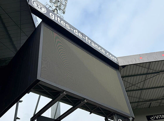
Der Mechanismus ist einfach: Kalte Luft senkt die Bildschirmoberflächentemperatur schnell, während die interne Platine, Lötstellen und Gehäusestruktur wärmer bleiben. Dieses Temperaturungleichgewicht erzeugt Spannungen durch Wärmeausdehnung und -kontraktion. Wiederholte Zyklen können Mikrorisse, PCB-Verformungen, Lötstellenermüdung oder schlechten Kontakt zwischen LEDs und Pads verursachen. Gleichzeitig erhöht der kalte Luftstrom die Wahrscheinlichkeit, dass Wasserdampf auf oder im Modul kondensiert.
- ▸Thermische Spannung – schnelle Abkühlung führt zu ungleichmäßiger Kontraktion zwischen LEDs, PCB, Lötstellen und Gehäusestrukturen.
- ▸Kondensationsgefahr – kalte Oberflächen lassen Feuchtigkeit in der Luft zu Wassertröpfchen kondensieren, was das Risiko von Leckagen und Kurzschlüssen erhöht.
- ▸Wiederkehrende Fehlerbereiche – wenn der Luftauslass immer auf denselben Bildschirmbereich bläst, fallen dieselben Module wiederholt aus.
Klimaanlagenauslässe sollten niemals direkt auf einen LED-Bildschirm blasen. Passen Sie die Luftstromrichtung an, installieren Sie Luftleitbleche oder ändern Sie die Position des Luftauslasses vor dem Langzeitbetrieb.
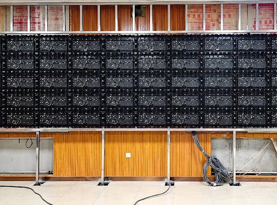
Stahlbaufabriken und -lager sind eine weitere Hochrisikoumgebung. In einem realen Projekt wurde ein Indoor-LED-Bildschirm an der Seitenwand eines Stahlgebäudes montiert. Hinter dem Bildschirm befand sich eine Stahl- oder Kunststoff-Stahlwandplatte. Kurz nach der Installation begannen Module, Netzteile und Empfängerkarten kurzzuschließen und durchzubrennen. Der anfängliche Verdacht galt der Produktqualität, aber die wahre Ursache war Kondensation.
Stahlkonstruktionen weisen große Temperaturunterschiede zwischen Tag und Nacht auf. Metallplatten kühlen schnell ab, während die feuchte Innenluft warm bleibt. Wenn warme, feuchte Luft eine kalte Stahloberfläche berührt, bildet sich Kondenswasser. Wenn der LED-Bildschirm ohne Belüftung dicht an der Stahlwand montiert ist, können Wassertröpfchen hinter dem Bildschirm, an Kabeln, in Netzteilen oder in der Nähe von Steckverbindern auftreten. Sobald Feuchtigkeit zu stromführenden Komponenten gelangt, sind Kurzschlüsse sehr wahrscheinlich.
- ▸Gekapselte Netzteil- und Kartenboxen verwenden – schützen Sie Netzteile, Empfängerkarten und Signalanschlüsse vor direkter Kondensation.
- ▸Kabel von unten nach oben verlegen – reduziert die Wahrscheinlichkeit, dass Wasser dem Kabel in Steckverbinder oder Elektrokästen folgt.
- ▸Belüftung hinter dem Bildschirm verbessern – vermeiden Sie versiegelte tote Räume, in denen sich warme feuchte Luft ansammelt und kondensiert.
LED-Bildschirme, die in KTV-Räumen, Bars, Clubs und Unterhaltungsstätten eingesetzt werden, sind einer anderen Art von Umweltrisiko ausgesetzt: Flüssigkeitsverunreinigungen. Getränke wie Bier, Milch, Softdrinks und sogar Reinigungswasser können auf die LED-Oberfläche spritzen. Einige Reinigungskräfte wischen den Bildschirm möglicherweise mit einem nassen Tuch ab oder spülen die Oberfläche sogar mit Leitungswasser ab. Diese Handlungen können schnell zu hellen Flecken, Raupenlinien, abnormalen Pixeln oder Modulausfällen führen.
Das Problem ist nicht nur das Wasser selbst. Leitungswasser, Getränke und Reinigungsflüssigkeiten enthalten leitfähige Ionen, Zucker, Mineralien oder Rückstände. Sobald sie in LED-Lötstellen, Lampenstrukturen, PCB-Spalte oder Steckverbinderbereiche gelangen, können sie Mikro-Kurzschlüsse verursachen. Nach der Verdunstung können verbleibende Rückstände weiterhin Feuchtigkeit aus der Luft aufnehmen und wiederholte Leckagen oder Korrosion verursachen.
Falls leitfähige Flüssigkeit auf einen LED-Bildschirm spritzt, sofort ausschalten. Den Betrieb nicht fortsetzen. Mit professionellem, nicht-ionischem LED-Bildschirmreiniger reinigen, vollständig trocknen, lüften und erst nach Überprüfung wieder einschalten.
In einigen Konferenzraumprojekten entwickeln neu installierte LED-Bildschirme eine dünne, nebelartige Schicht auf der Oberfläche, gefolgt von großen Bereichen mit toten Pixeln oder Raupenmustern. In einem Fall war die Ursache nicht das Displaymodul selbst, sondern die Kombination aus hoher Innenraumfeuchtigkeit, einer schrankartigen Klimaanlage hinter dem Bildschirm und einem inkonsistenten Betrieb zwischen lokalen und zentralen Klimaanlagen.
Wenn die Temperaturunterschiede nahe oder über kritischen Schwellenwerten liegen und die relative Luftfeuchtigkeit hohe Werte erreicht, kann sich Kondenswasser auf der Rückseite der LED-Module oder im Inneren des Gehäuses bilden. Diese Feuchtigkeit sammelt sich allmählich an und kann als „Wasservorhang“-Effekt erscheinen, der die LEDs von hinten beschädigt. Selbst wenn die Raumluftfeuchtigkeit unter 75 % liegt, kann ein großer lokaler Temperaturunterschied dennoch Kondensation auslösen.
- ▸Lokale Temperaturunterschiede unter Kontrolle halten – vermeiden Sie große Temperaturunterschiede zwischen Vorder-, Rück- und Seitenbereichen des LED-Bildschirms.
- ▸Entfeuchtung bei hoher Luftfeuchtigkeit einsetzen – sobald die relative Luftfeuchtigkeit 75 % erreicht, Luftentfeuchter oder den Trocknungsmodus der Klimaanlage verwenden.
- ▸Isolierte Kühlsysteme vermeiden – inkonsistenter Klimaanlagenbetrieb kann kalte Zonen und Kondensationsgefahr hinter dem Bildschirm verursachen.
Feuchtigkeit ist nicht die einzige Umweltbedrohung. In trockenen nördlichen Regionen oder Innenräumen mit geringer Luftfeuchtigkeit kann statische Elektrizität LEDs und Treiberschaltungen beschädigen. In einem Fall entwickelte ein in einem trockenen Bereich installierter Bildschirm eine große Anzahl raupenartiger Fehler. Nach Demontage und Inspektion fanden Techniker deutliche Stromverbrennungsspuren auf der Rückseite der LEDs.
Die Ursache lag in Leckströmen und schlechter Erdung. Einige Netzteile enthalten EMI-Filterkondensatoren, die zwischen stromführenden Leitern und Masse angeschlossen sind. Im Normalbetrieb kann ein kleiner Leckstrom auftreten. Wenn das LED-Bildschirmgehäuse nicht ordnungsgemäß geerdet ist, hat dieser Strom keinen sicheren Entladungspfad. In Kombination mit statischer Elektrizität kann dies ICs, LED-Chips oder Modulschaltungen beschädigen.
Statische Entladung ist der unsichtbare Angreifer; eine ordnungsgemäße Erdung ist der günstigste Schutz. Jedes LED-Display-Projekt sollte vor der Endabnahme den Erdungswiderstand, die Durchgängigkeit und den Potenzialausgleich überprüfen.
In Küsten- und Flussufergebieten liegt die relative Luftfeuchtigkeit oft über 80 %, insbesondere während des Rückzugs des Südwetters oder saisonaler Feuchtigkeitsspitzen. Küstenwind enthält auch Chloridsalzpartikel. Wenn Feuchtigkeit, Kondensation und Salznebel an LED-Leiterplatten, LED-Pins, Steckverbindern, Schrauben oder Lötstellen haften, bilden sie eine Elektrolytschicht. Unter elektrischen Feldern beschleunigt dies die elektrochemische Korrosion und die elektrische Migration.
- ▸Elektrodenmigration – Metallionen wie Silber oder Kupfer wandern zwischen positiven und negativen Elektroden und bilden dendritenartige leitende Pfade. Dies kann Leckagen, Kurzschlüsse und helle „Raupenmuster“ verursachen.
- ▸Verringerung des Isolationswiderstands – absorbiertes Salz senkt den Oberflächenwiderstand der Leiterplatte, was zu Signalstörungen und Anomalien des Treiber-ICs führt.
- ▸Metallkorrosion – Steckverbinder, Schrauben, Lötstellen und freiliegende Hardware können rosten, sich lösen oder den elektrischen Kontakt verlieren.
Der Raupeneffekt hängt eng mit der LED-Gehäusestruktur und dem Elektrodenabstand zusammen. Jedes LED-Gehäuse enthält rot, grün und blau leuchtende Chips, die intern verbunden sind. In feuchten Umgebungen kann Feuchtigkeit in das Gehäuse eindringen. Wenn der Abstand zwischen den Chipelektroden zu gering ist, wird die elektrochemische Migration erleichtert. Daher können bei LED-Projekten an Küsten größere LED-Gehäuse eine bessere Beständigkeit bieten, da sie den physikalischen Abstand zwischen den internen Elektroden vergrößern und einen dickeren Kapselungsschutz bieten.
Für LED-Display-Projekte an Küsten- und Flussufern wählen Sie größere LED-Gehäusegrößen, wenn der Pixelabstand dies zulässt. Wenn beispielsweise beide Lösungen die Auflösungsanforderung erfüllen, bietet ein größeres Gehäuse wie 2727 möglicherweise eine bessere Feuchtigkeitsbeständigkeit als kleinere Gehäuse wie 1921.
Die Vermeidung von Umweltschäden beginnt vor der Installation. Die richtige LED-Display-Lösung sollte basierend auf dem Projektstandort, der Luftfeuchtigkeit, der Belüftung, der Installationsstruktur, den Wasserdichtigkeitsanforderungen, der Salznebelexposition und den Wartungsbedingungen ausgewählt werden. In feuchten und küstennahen Gebieten sollten Käufer nicht nur Helligkeit und Pixelabstand vergleichen, sondern auch die Gehäusegröße, Feuchtigkeitsbeständigkeit, Schutzlackierung, strukturelle Abdichtung, Erdung und langfristige Wartungsfreundlichkeit bewerten.
Bevor Sie ein LED-Display in feuchten, küstennahen, stahlkonstruierten, Unterhaltungs- oder klimatisierten Umgebungen installieren, überprüfen Sie die folgenden Punkte:
- ✓ Vermeiden Sie direkten Klimaanlagen-Luftstrom auf die Oberfläche des LED-Bildschirms.
- ✓ Verwenden Sie IP65- oder höhere LED-Module, wo das Risiko von Wasser, Regen, Staub oder Feuchtigkeit hoch ist.
- ✓ Verwenden Sie eine Schutzlackierung für Leiterplatten, um Feuchtigkeit, Salznebel und Schimmelbildung zu vermeiden.
- ✓ Fügen Sie Temperatur- und Feuchtigkeitsüberwachung in Bildschirmstrukturen oder versiegelten Räumen hinzu.
- ✓ Installieren Sie Belüftung, Axialventilatoren, Entfeuchter oder Klimaanlagen, wo sich hohe Luftfeuchtigkeit ansammelt.
- ✓ Verwenden Sie Anti-Kondensationsheizungen oder thermostatische Steuerung, wenn die Temperaturunterschiede groß sind.
- ✓ Entwerfen Sie Stahlkonstruktionen mit Entwässerungskanälen und vermeiden Sie wasseransammelnde Vertiefungen.
- ✓ Schalten Sie das Gerät nicht sofort nach starker Feuchtigkeit, Regen oder Kondensation ein. Zuerst trocknen und prüfen.
- ✓ Verwenden Sie flammhemmende, feuchtigkeitsbeständige Materialien wie PC+Glasfaser-Kunststoffe und geschützte Netzteile.
- ✓ Überprüfen Sie Erdung, Antistatikmaßnahmen und Potenzialausgleich vor dem Betrieb.
Für LED-Display-Projekte in feuchten, küstennahen, stark frequentierten, klimatisierten oder installationsempfindlichen Umgebungen bietet VMX Visual LED-Display-Lösungen mit praktischem Fokus auf Zuverlässigkeit, Struktur, Wärmemanagement, Schutz und langfristige Wartungsfreundlichkeit.
Verwandte VMX Visual Seiten
- Outdoor LED-Displays – LED-Display-Lösungen für wetterexponierte und Outdoor-Werbeanwendungen
- Kommerzielle Indoor-LED-Displays – Feinpixel-Indoor-LED-Displays für kommerzielle und Konferenzraumbereiche
- Bühnenmiet-LED-Displays – LED-Display-Lösungen für Eventvermietungen und Umgebungen mit hoher Beanspruchung


Teilen:
Full Flip Chip COB LED Display erklärt | COB vs. SMD & Flip Chip Vorteile
LED Display Power Supply Guide: Prevent Hardware Failure & Surges